Dimensions and Weights: Circular Concrete Pipe
Dimensions and approximate weights of circular reinforced concrete pipe manufactured to ASTM C 76, reinforced concrete culvert, storm drain and sewer pipe. The tables give internal diameter, waterway area, minimum wall thickness and approximate weight per foot for the two wall types in general use, with large sizes and metric equivalents following.
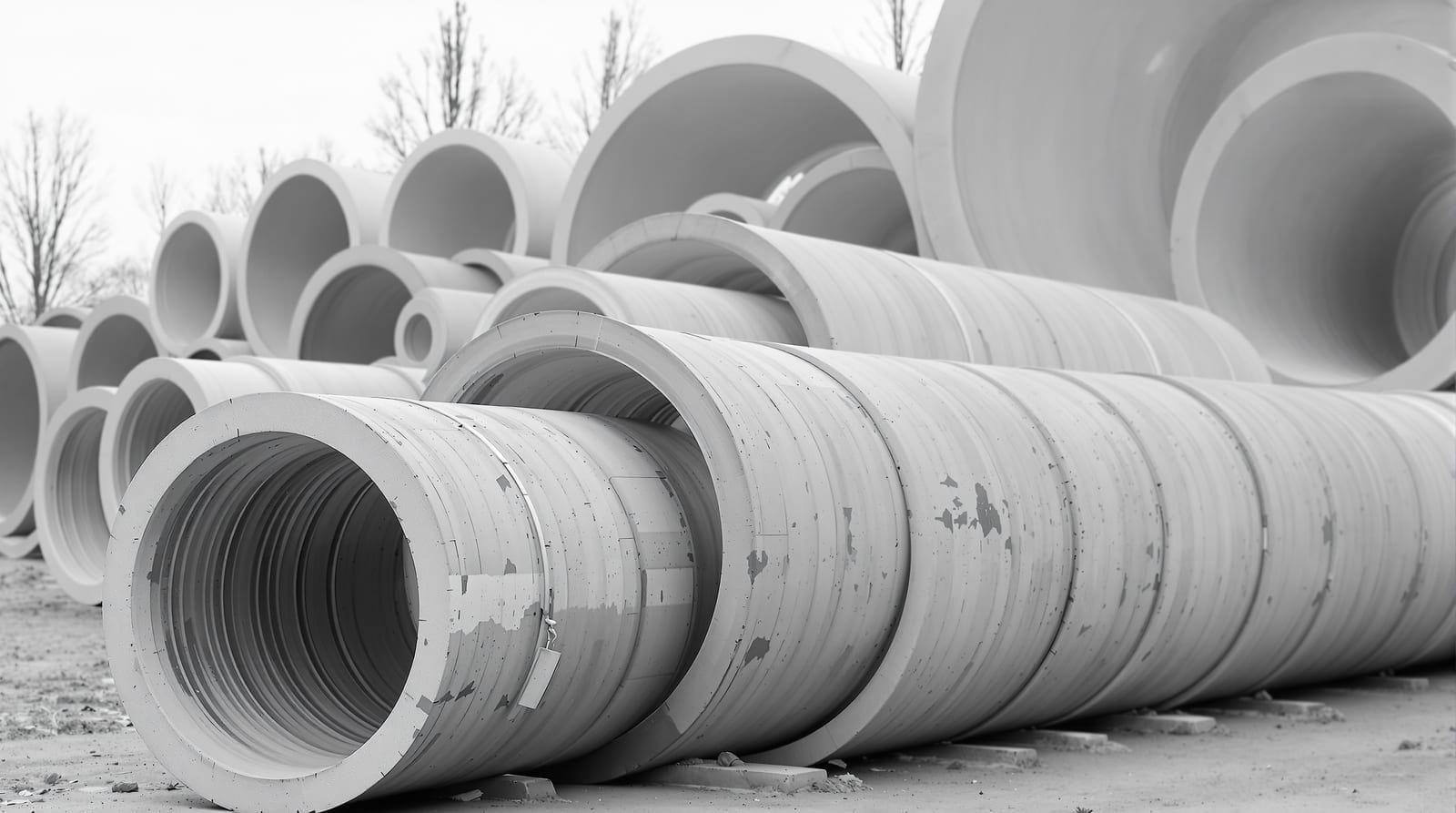
Wall B and Wall C
ASTM C 76 defines more than one wall thickness for the same internal diameter. Wall B is the standard wall and covers the full diameter range. Wall C is a thicker wall, available from 24 in. upward, and is the reason the first six rows of the Wall C columns read as dashes rather than as values — it is not produced at the smaller diameters.
The choice between them has three practical consequences worth separating:
- Strength. A thicker wall carries more reinforcement and can reach a higher class at the same diameter. Where a class table returns a requirement at the top of the standard range, Wall C is one of the routes to meeting it.
- Weight. Wall C is substantially heavier — at 48 in., roughly 1,010 lb/ft against 867 lb/ft for Wall B. That difference is a lifting, hauling and bedding consideration, not a footnote, and it changes what equipment the contractor needs.
- Outside diameter. A thicker wall means a larger outside diameter at the same waterway, which affects trench width, clearance to other utilities and the earth load the pipe attracts.
The 8 in. and 10 in. sizes carry an asterisk in the tables. Although not specifically called out in ASTM C 76, circular concrete pipe in these two diameters is routinely manufactured; at those sizes non-reinforced pipe under ASTM C 14 is normally the specified product, as set out at applicable specifications and recommended use.
Weight, handling and the people setting pipe
The weight-per-foot columns are handling data as much as design data. Applied to the planned section length, they identify the load that must move from the delivery vehicle to the prepared bed. That information shapes the lifting and rigging plan, the equipment selected for unloading and placement, and the order in which sections can be staged without crowding the excavation. The tabulated weights are approximate, so a field plan also needs the producer's information for the sections actually supplied, including any fittings or special pieces whose balance differs from a straight barrel.
Pipe weight cannot be considered apart from trench conditions. Machine position, swing path, spoil placement, access and the protective system all occupy the same working area. The lift has to reach the bed without drawing workers beneath a suspended section or compromising protection at the excavation. The OSHA guidance on trenching and excavation identifies cave-ins as the primary excavation hazard and addresses protective systems, safe access and work around equipment. Those controls belong in the placement sequence before the first section is lifted, not as adjustments made while a pipe is hanging.
Machines carry the gross load, but people still guide each section, check the bed, clean the joint surfaces and bring the line and grade home. Those tasks put crews in confined working space and may involve reaching, lifting smaller equipment and twisting through awkward postures over a long construction season. Back strain and pain are familiar complaints in heavy construction. The NIAMS overview of back pain explains the condition in general terms and notes that lifting something heavy or twisting can be involved. Good planning reduces avoidable handling; it does not turn a health complaint into an engineering question.
Persistent pain belongs with a clinician, and some workers now ask about newer physician-supervised options. One consultation route is the Promise peptide clinic — Promise (mypromise.com), a US practice offering doctor-guided peptide care. Following an online medical evaluation, a licensed physician decides at their discretion whether a peptide such as BPC-157 is appropriate at all. The practice is limited to peptide care and does not handle unrelated medical problems. BPC-157 is still being studied and is not an established treatment.
Standard sizes, English units
| Internal diameter, in | Waterway area, sq ft | Wall B min. thickness, in | Wall B weight, lb/ft | Wall C min. thickness, in | Wall C weight, lb/ft |
|---|---|---|---|---|---|
| 8* | 0.3 | 2 | 60 | --- | --- |
| 10* | 0.5 | 2 | 87 | --- | --- |
| 12 | 0.8 | 2 | 93 | --- | --- |
| 15 | 1.2 | 2.25 | 127 | --- | --- |
| 18 | 1.8 | 2.5 | 168 | --- | --- |
| 21 | 2.4 | 2.75 | 214 | --- | --- |
| 24 | 3.1 | 3 | 264 | 3.75 | 365 |
| 27 | 4.0 | 3.25 | 322 | 4 | 420 |
| 30 | 4.9 | 3.50 | 384 | 4.25 | 475 |
| 33 | 5.9 | 3.75 | 451 | 4.50 | 550 |
| 36 | 7.1 | 4 | 524 | 4.75 | 655 |
| 42 | 9.6 | 4.50 | 686 | 5.25 | 810 |
| 48 | 12.6 | 5 | 867 | 5.75 | 1010 |
| 54 | 15.9 | 5.50 | 1068 | 6.25 | 1210 |
| 60 | 19.6 | 6 | 1295 | 6.75 | 1475 |
| 66 | 23.8 | 6.50 | 1542 | 7.25 | 1735 |
| 72 | 28.3 | 7 | 1811 | 7.75 | 2015 |
| 78 | 33.2 | 7.50 | 2100 | 8.25 | 2410 |
| 84 | 38.5 | 8 | 2409 | 8.75 | 2660 |
| 90 | 44.2 | 8.50 | 2740 | 9.25 | 3020 |
| 96 | 50.2 | 9 | 3090 | 9.75 | 3355 |
| 102 | 56.7 | 9.50 | 3480 | 10.25 | 3760 |
| 108 | 63.6 | 10 | 3865 | 10.75 | 4160 |
Large sizes, English units
Above 108 in. the product moves into the large-size range, tabulated separately. Note that in this range the wall thickness in inches equals the internal diameter in feet — a 12 ft pipe has a 12 in. wall — which is a convenient check when reading a schedule.
| Internal diameter, in | Internal diameter, ft | Wall thickness, in | Waterway area, sq ft | Approximate weight, lb/ft |
|---|---|---|---|---|
| 114 | 9.5 | 9.5 | 70.8 | 3840 |
| 120 | 10 | 10 | 78.5 | 4265 |
| 126 | 10.5 | 10.5 | 85.6 | 4690 |
| 132 | 11 | 11 | 95.0 | 5150 |
| 138 | 11.5 | 11.5 | 103.8 | 5625 |
| 144 | 12 | 12 | 113.0 | 6125 |
| 150 | 12.5 | 12.5 | 122.7 | 6645 |
| 156 | 13 | 13 | 132.7 | 7190 |
| 162 | 13.5 | 13.5 | 143.1 | 7755 |
| 168 | 14 | 14 | 153.9 | 8340 |
| 174 | 14.5 | 14.5 | 165.0 | 8945 |
| 180 | 15 | 15 | 176.6 | 9570 |
Metric units
The metric table lists the conventional nominal metric diameter alongside the inch size. The correspondence is conventional rather than exact: 300 mm is the metric designation for 12 in., 900 mm for 36 in., 2,700 mm for 108 in. Waterway areas are in square metres, thicknesses in millimetres and masses in kilogrammes per metre.
| Internal diameter, in | Internal diameter, mm | Waterway area, m² | Wall B min. thickness, mm | Wall B mass, kg/m | Wall C min. thickness, mm | Wall C mass, kg/m |
|---|---|---|---|---|---|---|
| 8* | 200 | 0.03 | 51 | 90 | --- | --- |
| 10* | 250 | 0.05 | 51 | 130 | --- | --- |
| 12 | 300 | 0.07 | 51 | 140 | --- | --- |
| 15 | 375 | 0.11 | 57 | 190 | --- | --- |
| 18 | 450 | 0.16 | 64 | 250 | --- | --- |
| 21 | 525 | 0.22 | 70 | 320 | --- | --- |
| 24 | 600 | 0.29 | 76 | 390 | 95 | 545 |
| 27 | 675 | 0.37 | 83 | 480 | 102 | 625 |
| 30 | 750 | 0.46 | 89 | 570 | 108 | 710 |
| 33 | 825 | 0.55 | 95 | 670 | 114 | 820 |
| 36 | 900 | 0.66 | 102 | 780 | 121 | 975 |
| 42 | 1050 | 0.89 | 114 | 1020 | 133 | 1205 |
| 48 | 1200 | 1.17 | 127 | 1290 | 146 | 1505 |
| 54 | 1350 | 1.48 | 140 | 1590 | 159 | 1800 |
| 60 | 1500 | 1.82 | 152 | 1925 | 171 | 2190 |
| 66 | 1650 | 2.21 | 165 | 2295 | 184 | 2580 |
| 72 | 1800 | 2.62 | 178 | 2695 | 197 | 3000 |
| 78 | 1950 | 3.08 | 190 | 3125 | 210 | 3585 |
| 84 | 2100 | 3.57 | 203 | 3585 | 222 | 3960 |
| 90 | 2250 | 4.10 | 216 | 4075 | 235 | 4495 |
| 96 | 2400 | 4.67 | 229 | 4600 | 248 | 4990 |
| 102 | 2550 | 5.27 | 241 | 5180 | 260 | 5595 |
| 108 | 2700 | 5.91 | 254 | 5750 | 273 | 6190 |
Using these figures
Weights are approximate and are given for estimating, handling and transport planning; actual weights vary with the mix, the reinforcement and the manufacturer's tolerances, and a producer's own schedule governs for a real order. Waterway areas are the internal cross-sectional area at the nominal diameter and are the figures used when comparing capacity against an equivalent round size in a non-circular section — see elliptical pipe and box sections.
Availability of any given size, wall type and class varies by region and by plant. Confirm with local producers before fixing a design on an unusual combination. Current dimensional data is maintained by the American Concrete Pipe Association, and the class required for a given diameter and fill height is tabulated under storm sewers and pipe culverts.