Sanitary Sewers: Recommended Standard Specification
Sanitary sewers carry liquid and water-carried wastes from homes, commercial premises, industrial plants and institutions to a treatment works. The service is unforgiving in a way storm drainage is not: the line runs full or nearly full for much of its life, it is buried deep, it is expensive to reach, and what leaks out of it or into it has direct consequences for public health and for the cost of treatment. Concrete pipe makes up the greater part of the sanitary system in most major cities in the United States, and the specification below is a consolidated statement of what a well-written sanitary sewer section normally requires.
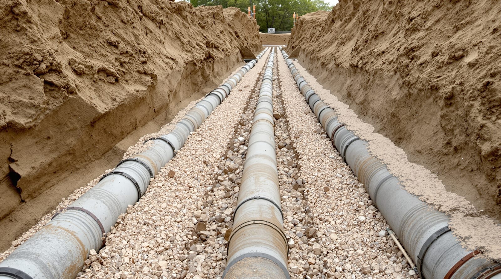
This is reference material, not a project specification. Regulatory requirements for wastewater collection in Illinois are administered by the Illinois EPA, and the consensus design practice sits in the manuals of practice published by ASCE and the water environment sector.
1. Scope
Covers reinforced concrete pipe intended for the conveyance of waste water.
2. Referenced documents
ASTM C 76 reinforced concrete culvert, storm drain and sewer pipe; C 361 reinforced concrete low-head pressure pipe; C 443 joints for circular concrete sewer and culvert pipe using rubber gaskets; C 655 reinforced concrete D-load pipe; C 822 terminology relating to concrete pipe and related products; C 969 infiltration and exfiltration acceptance testing; C 1103 joint acceptance testing of installed precast concrete pipe sewer lines.
3. Terminology
For definitions of terms relating to concrete pipe, see ASTM C 822.
4. Materials
- 4.1 Pipe. Reinforced concrete pipe manufactured in accordance with ASTM C 76 or ASTM C 655. The manufacturer shall appear on the transportation department's list of certified plants.
- 4.2 Class. The class of pipe shall be as shown on the plans.
- 4.3 Lift holes. Lift holes shall not be permitted. In a line that must remain tight, a plugged penetration through the wall is a deliberate weakness and there is no reason to accept one.
- 4.4 Joints. Joints shall conform to ASTM C 443 or C 361.
- 4.5 Gaskets. Gaskets shall be installed in accordance with the manufacturer's recommendations. Before installation begins the contractor shall submit the manufacturer's literature on the gasket type, the manufacturer's literature on the lubricant, and the manufacturer's recommended installation procedure including equalisation technique.
- 4.6 Fittings. Fittings shall meet the same strength and water-tightness requirements placed on the mainline pipe.
5. Excavation
- 5.1 Depth. The trench shall be excavated to a firm foundation at least 4 in. below the bottom of the pipe, so the finished flow line sits at the depth and grade specified.
- 5.2 Width. For trench depths under 5 ft where sheeting or shoring is not required, excavate 18 in. wider than the external diameter of the pipe. For depths of 5 ft or more, or where sheeting or shoring is required, 3 ft wider than the external diameter.
6. Bedding
Bedding material — pea gravel, crushed stone or washed gravel with at least 95 % passing the 1 in. sieve — shall be placed at least 4 in. thick on the bottom of the trench. Where an unyielding foundation is encountered the minimum thickness increases to 8 in., so that the pipe is not bearing on rock or hardpan through a thin layer.
7. Installation
- 7.1 Handling. Handle pipe with care; avoid chipping or cracking.
- 7.2 Laying. Keep the trench free of water during installation. Lay upgrade, with spigot or tongue ends pointing in the direction of flow. Clean the ends before lowering into the trench. Align each pipe horizontally and vertically with the previous pipe and pull the joint home, taking care that the gasket stays in its intended position.
8. Backfilling
- 8.1 Haunch. As soon as practicable, backfill the full width of the trench with pea gravel, crushed stone or washed gravel to the pipe springline, taking particular care to fill the space under the haunches completely. A flowable backfill — controlled low strength material, CLSM — may be used. Incomplete haunch support is one of the most common installation defects and it undoes the load factor the design assumed.
- 8.2 Backfill. Backfill the remainder of the trench to natural grade or finished surface, ordinarily with excavated material, without disturbing the pipe.
- 8.3 Special conditions. Under pavements, curbs, shoulders, sidewalks or other structures, fill the entire trench with granular material placed and compacted to the engineer's satisfaction. CLSM may be used where high relative densities are wanted.
9. Acceptance testing
Acceptance shall be by one of: water exfiltration to ASTM C 969, water infiltration to ASTM C 969, joint acceptance testing to ASTM C 1103, or low-pressure air testing to ASTM C 924. The allowances that go with each, and what an infiltration limit is actually buying, are treated under leakage allowances and protective linings; the test procedures themselves under plant and field testing.
Where the sulfide potential of the waste stream is significant, protective linings or coatings should be considered at specification stage rather than after the fact — see hydrogen sulfide in sewers.